

How Do I Clean Old Electric Insulators

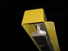
Ceramic insulator used on an electrified railway
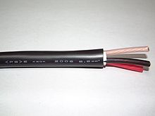
Three-core copper wire ability cable, each core with an individual colour-coded insulating sheath, all contained inside an outer protective sheath
An electrical insulator is a material in which electric electric current does not menstruum freely. The atoms of the insulator have tightly jump electrons which cannot readily movement. Other materials—semiconductors and conductors—conduct electric current more easily. The property that distinguishes an insulator is its resistivity; insulators have higher resistivity than semiconductors or conductors. The most mutual examples are non-metals.
A perfect insulator does non exist considering even insulators contain minor numbers of mobile charges (charge carriers) which can carry current. In addition, all insulators become electrically conductive when a sufficiently large voltage is applied that the electric field tears electrons away from the atoms. This is known as the breakup voltage of an insulator. Some materials such as glass, paper and PTFE, which accept high resistivity, are very good electrical insulators. A much larger class of materials, even though they may have lower bulk resistivity, are nonetheless good enough to prevent significant current from flowing at commonly used voltages, and thus are employed as insulation for electric wiring and cables. Examples include safe-like polymers and well-nigh plastics which tin can exist thermoset or thermoplastic in nature.
Insulators are used in electrical equipment to support and separate electrical conductors without allowing current through themselves. An insulating material used in bulk to wrap electrical cables or other equipment is called insulation. The term insulator is also used more specifically to refer to insulating supports used to adhere electric power distribution or transmission lines to utility poles and transmission towers. They back up the weight of the suspended wires without allowing the current to menses through the tower to ground.
Physics of conduction in solids [edit]
Electrical insulation is the absence of electric conduction. Electronic band theory (a co-operative of physics) dictates that a charge flows if states are available into which electrons tin can exist excited. This allows electrons to proceeds free energy and thereby move through a usher such as a metal. If no such states are available, the material is an insulator.
Virtually (though not all, see Mott insulator) insulators have a large band gap. This occurs considering the "valence" band containing the highest energy electrons is total, and a large energy gap separates this band from the next band above it. There is always some voltage (called the breakdown voltage) that gives electrons enough energy to be excited into this ring. Once this voltage is exceeded the material ceases beingness an insulator, and charge begins to laissez passer through it. However, it is unremarkably accompanied past physical or chemical changes that permanently degrade the material's insulating properties.
Materials that lack electron conduction are insulators if they lack other mobile charges too. For example, if a liquid or gas contains ions, then the ions can be made to flow as an electric current, and the fabric is a usher. Electrolytes and plasmas contain ions and act as conductors whether or not electron flow is involved.
Breakdown [edit]
When subjected to a high enough voltage, insulators endure from the miracle of electrical breakup. When the electric field applied across an insulating substance exceeds in any location the threshold breakdown field for that substance, the insulator suddenly becomes a conductor, causing a large increase in current, an electric arc through the substance. Electrical breakdown occurs when the electric field in the material is potent enough to advance gratuitous charge carriers (electrons and ions, which are always present at low concentrations) to a high enough velocity to knock electrons from atoms when they strike them, ionizing the atoms. These freed electrons and ions are in plough accelerated and strike other atoms, creating more charge carriers, in a chain reaction. Rapidly the insulator becomes filled with mobile charge carriers, and its resistance drops to a depression level. In a solid, the breakup voltage is proportional to the ring gap energy. When corona discharge occurs, the air in a region effectually a high-voltage conductor tin can break downwards and ionise without a catastrophic increase in electric current. However, if the region of air breakdown extends to another conductor at a dissimilar voltage it creates a conductive path betwixt them, and a large current flows through the air, creating an electric arc. Even a vacuum can endure a sort of breakup, but in this case the breakdown or vacuum arc involves charges ejected from the surface of metal electrodes rather than produced by the vacuum itself.
In addition, all insulators become conductors at very high temperatures as the thermal energy of the valence electrons is sufficient to put them in the conduction band.[ane] [2]
In sure capacitors, shorts between electrodes formed due to dielectric breakup tin disappear when the applied electric field is reduced.[3] [4] [5] [ relevant? ]
Uses [edit]
A very flexible coating of an insulator is oft applied to electric wire and cable; this assembly is called insulated wire. Wires sometimes don't employ an insulating coating, just air, since a solid (e.g. plastic) coating may be impractical. However, wires that affect each other produce cross connections, curt circuits, and burn hazards. In coaxial cablevision the center usher must be supported precisely in the middle of the hollow shield to forbid EM moving ridge reflections. Finally, wires that expose voltages college than lx V[ citation needed ] tin crusade human stupor and electrocution hazards. Insulating coatings help to prevent all of these problems.
Some wires have a mechanical covering with no voltage rating[ citation needed ]—e.g.: service-driblet, welding, doorbell, thermostat wire. An insulated wire or cable has a voltage rating and a maximum conductor temperature rating. It may not have an ampacity (electric current-conveying capacity) rating, since this is dependent upon the surrounding environment (e.g. ambient temperature).
In electronic systems, printed excursion boards are made from epoxy plastic and fibreglass. The nonconductive boards support layers of copper foil conductors. In electronic devices, the tiny and delicate active components are embedded within nonconductive epoxy or phenolic plastics, or within broiled glass or ceramic coatings.
In microelectronic components such as transistors and ICs, the silicon material is normally a conductor because of doping, only it tin can easily be selectively transformed into a expert insulator by the application of heat and oxygen. Oxidised silicon is quartz, i.e. silicon dioxide, the main component of glass.
In high voltage systems containing transformers and capacitors, liquid insulator oil is the typical method used for preventing arcs. The oil replaces air in spaces that must support meaning voltage without electrical breakdown. Other high voltage system insulation materials include ceramic or glass wire holders, gas, vacuum, and just placing wires far plenty apart to use air as insulation.
Insulation in electrical apparatus [edit]

The near important insulation material is air. A variety of solid, liquid, and gaseous insulators are too used in electrical apparatus. In smaller transformers, generators, and electric motors, insulation on the wire coils consists of upwardly to four thin layers of polymer varnish film. Movie-insulated magnet wire permits a manufacturer to obtain the maximum number of turns within the available space. Windings that use thicker conductors are often wrapped with supplemental fiberglass insulating tape. Windings may also exist impregnated with insulating varnishes to prevent electrical corona and reduce magnetically induced wire vibration. Large power transformer windings are still mostly insulated with paper, forest, varnish, and mineral oil; although these materials have been used for more than 100 years, they still provide a adept balance of economy and acceptable functioning. Busbars and circuit breakers in switchgear may be insulated with drinking glass-reinforced plastic insulation, treated to have depression flame spread and to foreclose tracking of current across the material.
In older apparatus made upward to the early 1970s, boards fabricated of compressed asbestos may be plant; while this is an adequate insulator at power frequencies, handling or repairs to asbestos cloth can release dangerous fibers into the air and must exist carried out cautiously. Wire insulated with felted asbestos was used in high-temperature and rugged applications from the 1920s. Wire of this type was sold by General Electric nether the trade name "Deltabeston."[half dozen]
Live-front switchboards up to the early part of the 20th century were made of slate or marble. Some loftier voltage equipment is designed to operate within a high force per unit area insulating gas such equally sulfur hexafluoride. Insulation materials that perform well at power and low frequencies may be unsatisfactory at radio frequency, due to heating from excessive dielectric dissipation.
Electric wires may be insulated with polyethylene, crosslinked polyethylene (either through electron axle processing or chemical crosslinking), PVC, Kapton, rubber-similar polymers, oil impregnated paper, Teflon, silicone, or modified ethylene tetrafluoroethylene (ETFE). Larger ability cables may use compressed inorganic pulverisation, depending on the application.
Flexible insulating materials such as PVC (polyvinyl chloride) are used to insulate the circuit and forestall human contact with a 'live' wire – one having voltage of 600 volts or less. Alternative materials are likely to become increasingly used due to Eu safety and environmental legislation making PVC less economical.
In electrical apparatus such every bit motors, generators, and transformers, various insulation systems are used, classified by their maximum recommended working temperature to achieve acceptable operating life. Materials range from upgraded types of paper to inorganic compounds.
Class I and Class II insulation [edit]
All portable or hand-held electrical devices are insulated to protect their user from harmful shock.
Class I insulation requires that the metal torso and other exposed metallic parts of the device be connected to earth via a grounding wire that is earthed at the main service panel—only only needs basic insulation on the conductors. This equipment needs an extra pin on the power plug for the grounding connexion.
Class Two insulation means that the device is double insulated. This is used on some appliances such as electric shavers, hair dryers and portable power tools. Double insulation requires that the devices take both basic and supplementary insulation, each of which is sufficient to forestall electric shock. All internal electrically energized components are totally enclosed within an insulated body that prevents any contact with "alive" parts. In the EU, double insulated appliances all are marked with a symbol of 2 squares, one inside the other.[7]
Telegraph and power manual insulators [edit]
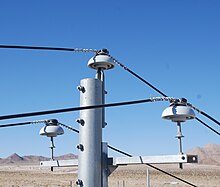
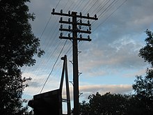
Power lines supported by ceramic pivot-blazon insulators in California, U.s.a.
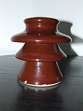
10 kV ceramic insulator, showing sheds
Overhead conductors for high-voltage electric power transmission are blank, and are insulated by the surrounding air. Conductors for lower voltages in distribution may take some insulation but are often blank as well. Insulating supports chosen insulators are required at the points where they are supported by utility poles or transmission towers. Insulators are also required where the wire enters buildings or electrical devices, such as transformers or circuit breakers, to insulate the wire from the instance. These hollow insulators with a conductor inside them are called bushings.
Material [edit]
Insulators used for high-voltage power transmission are made from glass, porcelain or composite polymer materials. Porcelain insulators are fabricated from clay, quartz or alumina and feldspar, and are covered with a smooth glaze to shed water. Insulators made from porcelain rich in alumina are used where loftier mechanical strength is a criterion. Porcelain has a dielectric forcefulness of about 4–10 kV/mm.[8] Glass has a higher dielectric force, but it attracts condensation and the thick irregular shapes needed for insulators are difficult to cast without internal strains.[ix] Some insulator manufacturers stopped making drinking glass insulators in the late 1960s, switching to ceramic materials.
Recently, some electrical utilities have begun converting to polymer composite materials for some types of insulators. These are typically composed of a central rod made of fibre reinforced plastic and an outer weathershed made of silicone rubber or ethylene propylene diene monomer safe (EPDM). Blended insulators are less costly, lighter in weight, and have excellent hydrophobic capability. This combination makes them platonic for service in polluted areas. However, these materials do not nonetheless accept the long-term proven service life of glass and porcelain.
Design [edit]
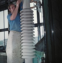
High voltage ceramic bushing during industry, before glazing (1977)
The electric breakup of an insulator due to excessive voltage can occur in one of two means:
- A puncture arc is a breakup and conduction of the material of the insulator, causing an electric arc through the interior of the insulator. The heat resulting from the arc commonly damages the insulator irreparably. Puncture voltage is the voltage beyond the insulator (when installed in its normal fashion) that causes a puncture arc.
- A flashover arc is a breakdown and conduction of the air around or along the surface of the insulator, causing an arc along the outside of the insulator. Insulators are usually designed to withstand flashover without damage. Flashover voltage is the voltage that causes a flash-over arc.
Most high voltage insulators are designed with a lower flashover voltage than puncture voltage, so they flash over before they puncture, to avoid impairment.
Dirt, pollution, salt, and particularly h2o on the surface of a high voltage insulator tin can create a conductive path beyond it, causing leakage currents and flashovers. The flashover voltage tin be reduced by more than than 50% when the insulator is wet. High voltage insulators for outdoor use are shaped to maximise the length of the leakage path along the surface from one end to the other, called the creepage length, to minimise these leakage currents.[x] To accomplish this the surface is moulded into a series of corrugations or concentric disc shapes. These normally include one or more sheds; downward facing loving cup-shaped surfaces that human action as umbrellas to ensure that the office of the surface leakage path nether the 'cup' stays dry out in wet conditions. Minimum creepage distances are 20–25 mm/kV, but must be increased in high pollution or airborne sea-common salt areas.
Types of insulators [edit]

A three-phase insulator used on distribution lines, typically thirteen.8 kV phase to phase. The lines are held in a diamond pattern, multiple insulators used betwixt poles.
These are the common classes of insulators:[ commendation needed ]
- Pivot insulator - Every bit the name suggests, the pin type insulator is mounted on a pin on the cross-arm on the pole. There is a groove on the upper end of the insulator. The conductor passes through this groove and is tied to the insulator with annealed wire of the aforementioned cloth as the conductor. Pin type insulators are used for transmission and distribution of communications, and electric power at voltages up to 33 kV. Insulators made for operating voltages betwixt 33 kV and 69 kV tend to exist very beefy and take go uneconomical in contempo years.
- Post insulator - A blazon of insulator in the 1930s that is more than compact than traditional pivot-blazon insulators and which has rapidly replaced many pin-type insulators on lines upward to 69 kV and in some configurations, can be made for operation at up to 115 kV.
- Suspension insulator - For voltages greater than 33 kV, it is a usual exercise to apply interruption type insulators, consisting of a number of drinking glass or porcelain discs connected in serial by metal links in the form of a string. The usher is suspended at the bottom cease of this cord while the height end is secured to the cross-arm of the tower. The number of disc units used depends on the voltage.
- Strain insulator - A dead end or anchor pole or belfry is used where a straight section of line ends, or angles off in another direction. These poles must withstand the lateral (horizontal) tension of the long direct section of wire. To back up this lateral load, strain insulators are used. For low voltage lines (less than 11 kV), shackle insulators are used as strain insulators. Yet, for loftier voltage transmission lines, strings of cap-and-pin (suspension) insulators are used, attached to the crossarm in a horizontal direction. When the tension load in lines is exceedingly high, such every bit at long river spans, 2 or more than strings are used in parallel.
- Shackle insulator - In early days, the shackle insulators were used as strain insulators. But nowaday, they are frequently used for depression voltage distribution lines. Such insulators can be used either in a horizontal position or in a vertical position. They tin can be direct fixed to the pole with a bolt or to the cross arm.
- Bushing - enables one or several conductors to laissez passer through a partition such as a wall or a tank, and insulates the conductors from it.[11]
- Line post insulator
- Station post insulator
- Cut-out
Sheath insulator [edit]
Bottom-contact third rail in a sheath insulator
An insulator that protects a total length of bottom-contact third rail.
| | This section needs expansion. Yous can help by adding to information technology. (April 2021) |
Suspension insulators [edit]
| Line voltage (kV) | Discs |
|---|---|
| 34.5 | iii |
| 69 | 4 |
| 115 | half-dozen |
| 138 | 8 |
| 161 | 11 |
| 230 | 14 |
| 287 | 15 |
| 345 | eighteen |
| 360 | 23 |
| 400 | 24 |
| 500 | 34 |
| 600 | 44 |
| 750 | 59 |
| 765 | sixty |

Intermission insulator string (the vertical string of discs) on a 275 kV suspension pylon

Suspended drinking glass disc insulator unit of measurement used in interruption insulator strings for high voltage transmission lines
Pin-type insulators are unsuitable for voltages greater than nigh 69 kV line-to-line. Higher transmission voltages use suspension insulator strings, which tin can be made for any practical manual voltage by calculation insulator elements to the cord.[13]
Higher voltage transmission lines usually employ modular interruption insulator designs. The wires are suspended from a 'string' of identical disc-shaped insulators that attach to each other with metal clevis pin or ball-and-socket links. The advantage of this design is that insulator strings with different breakdown voltages, for use with different line voltages, can be constructed by using different numbers of the basic units. Also, if one of the insulator units in the string breaks, it can be replaced without discarding the entire cord.
Each unit of measurement is synthetic of a ceramic or glass disc with a metallic cap and pin cemented to opposite sides. To make defective units obvious, glass units are designed so that an overvoltage causes a puncture arc through the glass instead of a flashover. The glass is heat-treated and then it shatters, making the damaged unit of measurement visible. However the mechanical strength of the unit is unchanged, so the insulator string stays together.
Standard suspension disc insulator units are 25 centimetres (nine.8 in) in bore and 15 cm (6 in) long, can support a load of lxxx–120 kilonewtons (18,000–27,000 lbf), have a dry flashover voltage of about 72 kV, and are rated at an operating voltage of ten–12 kV.[xiv] However, the flashover voltage of a string is less than the sum of its component discs, because the electric field is not distributed evenly beyond the string but is strongest at the disc nearest to the conductor, which flashes over kickoff. Metal grading rings are sometimes added around the disc at the high voltage end, to reduce the electric field across that disc and ameliorate flashover voltage.
In very loftier voltage lines the insulator may be surrounded by corona rings.[15] These typically consist of toruses of aluminium (most commonly) or copper tubing attached to the line. They are designed to reduce the electric field at the point where the insulator is attached to the line, to prevent corona discharge, which results in power losses.

History [edit]
The first electrical systems to make utilise of insulators were telegraph lines; straight attachment of wires to wooden poles was establish to give very poor results, especially during clammy conditions.
The first glass insulators used in large quantities had an unthreaded pinhole. These pieces of glass were positioned on a tapered wooden pivot, vertically extending upwards from the pole's crossarm (commonly simply two insulators to a pole and mayhap one on top of the pole itself). Natural contraction and expansion of the wires tied to these "threadless insulators" resulted in insulators unseating from their pins, requiring transmission reseating.
Amongst the first to produce ceramic insulators were companies in the United Kingdom, with Stiff and Doulton using stoneware from the mid-1840s, Joseph Bourne (later renamed Denby) producing them from around 1860 and Bullers from 1868. Utility patent number 48,906 was granted to Louis A. Cauvet on 25 July 1865 for a process to produce insulators with a threaded pinhole: pin-blazon insulators still accept threaded pinholes.
The invention of suspension-type insulators made loftier-voltage power transmission possible. As manual line voltages reached and passed 60,000 volts, the insulators required become very large and heavy, with insulators made for a safety margin of 88,000 volts being virtually the practical limit for manufacturing and installation. Interruption insulators, on the other hand, can be connected into strings as long as required for the line'southward voltage.
A large variety of telephone, telegraph and power insulators have been fabricated; some people collect them, both for their historic interest and for the aesthetic quality of many insulator designs and finishes. One collectors organization is the US National Insulator Clan, which has over 9,000 members.[16]
Insulation of antennas [edit]

Egg-shaped strain insulator
Often a broadcasting radio antenna is congenital every bit a mast radiator, which ways that the unabridged mast construction is energised with high voltage and must be insulated from the ground. Steatite mountings are used. They have to withstand non only the voltage of the mast radiator to ground, which can achieve values upward to 400 kV at some antennas, but besides the weight of the mast construction and dynamic forces. Arcing horns and lightning arresters are necessary because lightning strikes to the mast are common.
Guy wires supporting antenna masts usually take strain insulators inserted in the cablevision run, to keep the high voltages on the antenna from brusque circuiting to footing or creating a daze gamble. Ofttimes guy cables accept several insulators, placed to break up the cable into lengths that prevent unwanted electrical resonances in the guy. These insulators are usually ceramic and cylindrical or egg-shaped (see picture). This construction has the advantage that the ceramic is under compression rather than tension, so it can withstand greater load, and that if the insulator breaks, the cablevision ends are still linked.
These insulators also accept to be equipped with overvoltage protection equipment. For the dimensions of the guy insulation, static charges on guys have to exist considered. For high masts, these can be much college than the voltage caused past the transmitter, requiring guys divided by insulators in multiple sections on the highest masts. In this case, guys which are grounded at the anchor basements via a coil - or if possible, directly - are the better option.
Feedlines attaching antennas to radio equipment, peculiarly twin lead type, oftentimes must be kept at a altitude from metal structures. The insulated supports used for this purpose are called standoff insulators.
Encounter too [edit]
- Dielectric material
- Electrical conductivity
Notes [edit]
- ^ S. L. Kakani (one January 2005). Electronics Theory and Applications. New Age International. p. 7. ISBN978-81-224-1536-0.
- ^ Waygood, Adrian (19 June 2013). An Introduction to Electrical Science. Routledge. p. 41. ISBN978-1-135-07113-4.
- ^ Klein, Northward.; Gafni, H. (1966). "The maximum dielectric forcefulness of sparse silicon oxide films". IEEE Trans. Electron Devices. 13 (2): 281. Bibcode:1966ITED...13..281K. doi:10.1109/T-ED.1966.15681.
- ^ Inuishi, Y.; Powers, D.A. (1957). "Electrical breakdown and conduction through Mylar films". J. Appl. Phys. 58 (9): 1017–1022. Bibcode:1957JAP....28.1017I. doi:10.1063/1.1722899.
- ^ Belkin, A.; et., al. (2017). "Recovery of Alumina Nanocapacitors after High Voltage Breakdown". Scientific Reports. 7 (1): 932. Bibcode:2017NatSR...vii..932B. doi:10.1038/s41598-017-01007-9. PMC5430567. PMID 28428625.
- ^ Bernhard, Frank; Bernhard, Frank H. (1921). EMF Electrical Twelvemonth Book. Electrical Trade Pub. Co. p. 822.
- ^ "Understanding IEC Appliance Insulation Classes: I, II and III". Fidus Power. six July 2018.
- ^ "Electrical Porcelain Insulators" (PDF). Product spec sheet. Universal Clay Products, Ltd. Retrieved 2008-10-19 .
- ^ Cotton wool, H. (1958). The Transmission and Distribution of Electrical Energy. London: English Univ. Printing. copied on Insulator Usage, A.C. Walker's Insulator Information folio
- ^ Holtzhausen, J.P. "High Voltage Insulators" (PDF). IDC Technologies. Archived from the original (PDF) on 2014-05-14. Retrieved 2008-x-17 .
- ^ IEC 60137:2003. 'Insulated bushings for alternating voltages above ane,000 V.' IEC, 2003.
- ^ Diesendorf, W. (1974). Insulation Coordination in High Voltage Ability Systems. UK: Butterworth & Co. ISBN0-408-70464-0. reprinted on Overvoltage and flashovers, A. C. Walker's Insulator Data website
- ^ Donald 1000. Fink, H. Wayne Beaty (ed).,Standard Handbook for Electrical Engineers, 11th Edition, McGraw-Loma, 1978, ISBN 0-07-020974-X, pages xiv-153, 14-154
- ^ Grigsby, Leonard L. (2001). The Electric Power Engineering science Handbook. Usa: CRC Printing. ISBN0-8493-8578-four.
- ^ Bakshi, Yard (2007). Electric Power Manual and Distribution. Technical Publications. ISBN978-81-8431-271-3.
- ^ "Insulators : National Insulator Association Home Folio". www.nia.org . Retrieved 2017-12-12 .
References [edit]
- Taylor, Sue (May 2003). Bullers of Milton. ISBN978-one-897949-96-2.
- Function of Grading rings to Composite Insulator
- General Overview on Glass Insulators

Source: https://en.wikipedia.org/wiki/Insulator_(electricity)
Posted by: carrollkhorde.blogspot.com
0 Response to "How Do I Clean Old Electric Insulators"
Post a Comment